



Diodes Explained: Rectifier, Schottky, Zener, Flyback and How to Choose
Contents List
- Introduction.
- What Is a Diode and How Does It Work?.
- Types of Diodes.
- Polarity: Which End Is the Cathode?.
- Reading a Diode’s Ratings.
- Rectifier Circuits: Half-Wave and Bridge.
- Choosing a Rectifier Diode.
- Schottky Diodes.
- Zener Diodes and the Zener Regulator.
- The Flyback (Freewheeling) Diode.
- Reverse-Polarity Protection.
- TVS Diodes: Protection Against Surges.
- How to Test a Diode with a Multimeter.
- Common Mistakes to Avoid.
- Diodes to Keep in Your Kit.
- Frequently Asked Questions.
- Conclusion.
Time reading is 15min.
1. Introduction
A diode lets current flow in one direction and blocks it in the other. That simple idea turns AC into DC in every power adapter, protects a circuit from a reversed battery, absorbs the voltage spike of a relay coil, and holds a reference voltage steady. The 1N4007 is one of the best-selling parts in our store for a good reason: nearly every project needs at least one diode.
This guide explains how a diode works, how to read its polarity, the main types (rectifier, switching, Schottky, zener, fast recovery, bridge and TVS), what the voltage and current ratings mean, how rectifier circuits work, how to size a zener resistor, why a flyback diode saves your transistor, and how to test a diode with a multimeter. Every section has worked numbers you can check yourself.

1N4007 General Purpose Diode 1A 1.1V@1A 1kV DO-41

1N4148 Fast Switching Diode DO-35

1N5820 Schottky Diode 3A 20V 475mV@3A DO-201AD

1N4733A Zener Diode 5.1V 1W

KBP210 Bridge Rectifier Single-Phase 2A 1000V KBP-2
2. What Is a Diode and How Does It Work?
A diode has two terminals: the anode (A) and the cathode (K). When the anode is more positive than the cathode by more than a small voltage, the diode is forward biased and conducts. When the voltage is reversed, it is reverse biased and blocks, apart from a tiny leakage current.
- Forward voltage (Vf): the voltage the diode drops while it conducts. About 0.6 to 0.7 V for silicon, about 0.2 to 0.4 V for a Schottky diode.
- Reverse voltage rating (VR): the highest reverse voltage the diode can block before it breaks down. Exceeding it destroys a normal diode.
- Forward current rating (IF): the highest continuous current it can carry. The diode heats up as P = Vf × I.

The figure shows typical shapes. Notice that the diode is not an ideal switch: it needs its forward voltage before it conducts, and it wastes P = Vf × I as heat. A Schottky diode starts conducting earlier, so it wastes less.
3. Types of Diodes
Diodes are made for different jobs. Pick the type that matches the circuit:
| Type | Typical part | Main use | Browse |
|---|---|---|---|
| General-purpose rectifier | 1N4001 to 1N4007, 1N5399, 1N5408, 6A10 | Converting 50/60 Hz AC to DC, general blocking | General-purpose diodes |
| Switching (signal) diode | 1N4148, 1N4148W | Fast signal switching, logic protection, small currents | General-purpose diodes and SMD diodes |
| Schottky diode | 1N5819, 1N5820, SS16, SS36, BAT54 | Low voltage drop, fast switching, DC-DC converters, reverse protection | Schottky diodes |
| Zener diode | BZX55C series, 1N4733A | Voltage reference and clamping | Zener diodes |
| Fast and ultra-fast recovery | FR107, FR157, UF4007, US1M | Switching power supplies and inverters | Fast recovery diodes |
| Bridge rectifier | W04M, KBP210, KBL410 | Full-wave rectification in one package | Bridge rectifiers |
| TVS diode | P6KE series, SD12C | Surge and ESD protection | TVS diodes |
Rectifier and switching diodes
The 1N4007 is rated for 1 A and 1000 V reverse voltage, which is why it is used from small adapters to mains circuits. Higher-current versions in the same style include the 1N5399 (1.5 A), RL207 (2 A), 1N5408 (3 A) and 6A10 (6 A). The 1N4148 is a small, fast signal diode, rated for roughly 150 to 200 mA and 100 V, used for logic, protection and switching small loads.
1N4007 General Purpose Diode 1A 1.1V@1A 1kV DO-41

1N5399 Diode 1.5A 1000V

RL207 Rectifier Diode 2A 1kV 1V@2A DO-15

1N5408 Diode 3A 1000V

Rectifier Diode 6A 1000V 6A10
1N4148 Fast Switching Diode DO-35

1N4007 M7 SMA Diodes – General Purpose SMD 1A Single 1.1V@1A 1kV

SMD Switching Diode 1N4148W T4 100V Independent Type 1.25V@150mA 4ns 150mA SOD-123
Schottky, zener and fast recovery diodes
1N5820 Schottky Diode 3A 20V 475mV@3A DO-201AD

1N5711 Schottky Diode

Schottky Diode BAT43 30V 200mA Through Hole DO-35

SS16 SMA Schottky Barrier Diodes (SBD) SMD 60V 700mV@1A 1A
SS36 SMA Schottky Barrier Diodes (SBD) SMD 60V Single 0.7V@3A 3A
1N4733A Zener Diode 5.1V 1W

BZX55C6V2 Zener Diode 6.2V 0.5W

Zener Diode 3.3V 0.5W

Zener Diode 12V 0.5W

FR157 Fast Recovery Rectifier Diode 1000V 1.5A DO-15

BY255 Fast Recovery Rectifier Diode 3A 1300V DO-201AD
US1M SMA Diodes – Fast Recovery Rectifier SMD 1.65V@1A 75ns Single 1A 1kV
Bridge rectifiers and TVS diodes

Bridge Rectifier 1A W04M
KBP210 Bridge Rectifier Single-Phase 2A 1000V KBP-2

KBL406 Bridge Rectifier Single-Phase 4A 600V

Bridge Rectifier KBL1010 10A 1000V

ESD Suppressors / TVS Diodes 600W 12V Bi-directional P6KE12CA-E3/73
ESD Suppressors / TVS Diodes 600W 15V Uni-directional P6KE15A-E3/73

SD12C.TCT 12V Bidirectional TVS ESD Protection Diode SMD SOD-323
4. Polarity: Which End Is the Cathode?
A diode installed backwards does not work, so always find the cathode before you solder.
- Axial diodes (1N4007, 1N4148, 1N5819): a band near one end marks the cathode. On black plastic diodes the band is silver or white. On small glass diodes it is black or colored. Current flows from the end without the band to the end with the band.
- SMD diodes: a bar or stripe on one end marks the cathode. SOT-23 parts have the pin-out in the datasheet.
- Zener diodes follow the same rule: the band is the cathode, and in normal use the cathode connects to the more positive side because the zener works in reverse.
- Bridge rectifiers have four terminals marked AC, AC, + and −. The two AC pins take the AC input, the + pin is the positive DC output and the − pin is the negative output. A square corner or a longer lead often marks the positive pin.
In a circuit diagram the diode symbol is a triangle pointing in the direction of the conventional current, towards a bar. The bar is the cathode.
5. Reading a Diode’s Ratings
When you choose a diode, look at four numbers on the datasheet or in the product title:
| Rating | Meaning | How to choose |
|---|---|---|
| VR (or VRRM) | Maximum reverse voltage | At least 1.5 to 2 times the highest reverse voltage in the circuit |
| IF (or IO) | Maximum average forward current | At least 1.5 to 2 times the load current |
| Vf | Forward voltage drop at a given current | Lower is better for efficiency (Schottky) |
| trr | Reverse recovery time (speed) | Short for switching circuits (tens of nanoseconds or less) |
Example from our listings: a 1N4007 is shown as 1 A, 1.1 V at 1 A and 1 kV. That means it can block up to 1000 V in reverse, carry 1 A continuously, and drops up to 1.1 V at 1 A, so it dissipates up to about 1.1 W at that current. A 1N5820 is 3 A, 20 V and about 475 mV at 3 A: much less drop, but only 20 V of reverse voltage. An SS16 is 1 A and 60 V.
6. Rectifier Circuits: Half-Wave and Bridge
A rectifier converts AC to pulsating DC. A half-wave rectifier uses one diode and passes only the positive half-cycles. A bridge uses four diodes and passes both half-cycles, flipping the negative one to positive.

- Peak voltage: the peak of an AC supply is RMS × 1.414. A 12 V AC transformer gives a peak of about 17 V, and 220 V mains gives about 311 V.
- Bridge drop: current passes through two diodes at a time, so the DC output is lower by about 2 × Vf. With silicon diodes that is about 1.4 V: a 12 V AC supply gives about 17 − 1.4 ≈ 15.6 V peak DC before smoothing.
- Ripple frequency: the output has 100 pulses per second from a 50 Hz supply with a bridge, and 50 pulses with a half-wave rectifier, so a bridge is easier to smooth.
- Rating: choose a diode or bridge whose VR is well above the peak voltage, and whose current rating is at least twice the load current.
After the rectifier, a smoothing capacitor fills the gaps. The size of the capacitor and the ripple formula are explained in our capacitors guide. A 1N4007 bridge or a ready-made bridge such as the KBP210 (2 A) or KBL410 (4 A) is enough for most small adapters. Always check the load current before choosing.
7. Choosing a Rectifier Diode
- For mains frequency (50/60 Hz): a 1N400x diode is the standard choice. Use 1N4007 when in doubt, because its 1000 V rating covers all of the family’s uses.
- For more current: step up to the 1N5399 (1.5 A), RL207 (2 A), 1N5408 (3 A) or 6A10 (6 A), or use a bridge rectifier with a heat sink for 10 A and above.
- For switching power supplies and fast signals: do not use 1N400x diodes. They are slow rectifiers. Use a fast recovery diode (FR107, FR157, UF4007) or a Schottky diode.
- For small signals: a 1N4148 (or 1N4148W in SMD) is the standard switching diode.
Mount high-current diodes with space around them, because the heat equals Vf × I. For example a 3 A diode with 0.9 V forward drop dissipates about 2.7 W and becomes very hot without a heat sink or copper area.
8. Schottky Diodes
A Schottky diode uses a metal-semiconductor junction instead of the usual P-N junction. This gives it a low forward voltage (typically 0.2 to 0.4 V) and very fast switching.
- Advantages: lower loss, higher efficiency, no reverse recovery delay, ideal in DC-DC converters and as the freewheeling diode in switching supplies.
- Drawbacks: lower maximum reverse voltage (commonly 20 V to 100 V, with some up to 200 V) and a higher leakage current that increases with temperature.
- Typical uses: reverse-polarity protection with low drop, OR-ing two supplies, solar and battery circuits, and rectifiers in low-voltage supplies.
Compare the power wasted by a protection diode carrying 2 A: a silicon diode at 0.7 V wastes 0.7 × 2 = 1.4 W, and a Schottky diode at about 0.35 V wastes about 0.7 W. Schottky parts such as the 1N5820 (3 A, 20 V), SS16 (1 A, 60 V) and SS36 (3 A, 60 V) are available in our Schottky diode and SMD Schottky ranges.
9. Zener Diodes and the Zener Regulator
A zener diode is designed to conduct in the reverse direction at a defined voltage, called the zener voltage (Vz), such as 3.3 V, 5.1 V, 6.2 V or 12 V. Above Vz the voltage across it stays almost constant, so it can hold a reference voltage or clamp a signal.
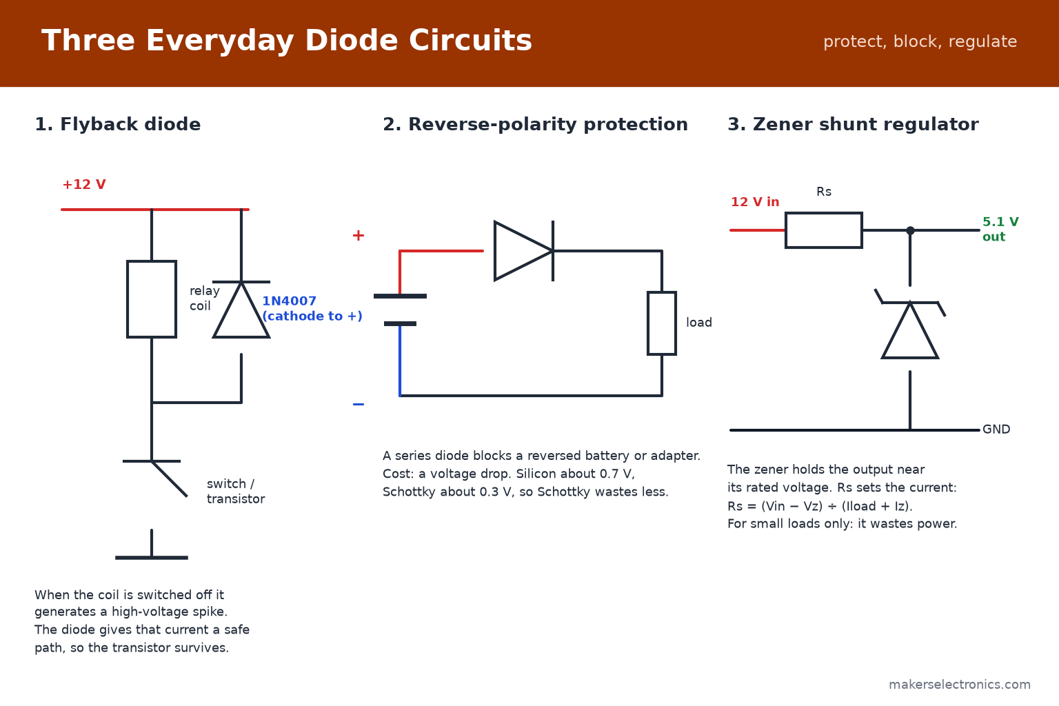
A simple shunt regulator uses a series resistor Rs and the zener across the output (see circuit 3 in the figure):
Rs = (Vin − Vz) ÷ (Iload + Iz)
Example: 12 V in, 5.1 V zener, a load of 10 mA, and 10 mA through the zener to keep it regulating. Rs = (12 − 5.1) ÷ 0.020 = 345 Ω, so use 330 Ω. The total current is then (12 − 5.1) ÷ 330 ≈ 20.9 mA. The resistor dissipates 0.0209² × 330 ≈ 0.14 W, and if the load is removed the zener carries all 20.9 mA, so it dissipates about 5.1 × 0.0209 ≈ 0.11 W. A 0.25 W resistor and a 0.5 W zener are enough.
A zener regulator wastes power and the output changes with the load, so use it only for small, steady loads or as a reference. For real power, use a regulator IC or a buck converter: see our buck converter vs LDO guide. Zeners are also used to protect inputs: a 3.3 V zener across an input to ground clamps a 5 V signal from damaging a 3.3 V pin (with a series resistor).
10. The Flyback (Freewheeling) Diode
A relay coil, a motor and a solenoid are inductors. When you switch them off, the current cannot stop instantly, so the coil produces a high-voltage spike that can destroy the transistor or the microcontroller pin. A flyback diode placed across the coil gives that current a safe path (circuit 1 in the figure above).
- Direction: the diode is connected in reverse across the coil: the cathode goes to the positive supply and the anode to the switched side. In normal operation it does not conduct.
- Which diode: a 1N4007 or 1N4148 works for relays and small motors. For fast switching or PWM-driven motors, a Schottky or fast recovery diode copes better.
- Where: place it as close to the coil as possible.
- Note: many relay modules already include this diode. The diode makes the relay release a little slower, which is normal.
The same protection is needed for DC motors and solenoids driven from Arduino or ESP32 pins through a transistor or MOSFET. See our transistors guide for driving loads.
11. Reverse-Polarity Protection
If you power a device from a battery or an adapter, plugging it in backwards can destroy it. The simplest protection is a series diode in the positive line (circuit 2 in the figure). Current flows normally, and a reversed supply is blocked.
- Cost: the diode drops its forward voltage all the time. With silicon it is about 0.7 V, with a Schottky diode about 0.3 V. On a 5 V supply that matters.
- Current rating: the diode carries the whole load current, so choose it for at least twice the load.
- Alternative: for high currents or low voltages, a P-channel MOSFET in the positive line has a much smaller drop.
Example: a device drawing 1 A from a 12 V adapter with a 1N5819 (Schottky, roughly 0.5 V at 1 A) loses about 0.5 W and sees about 11.5 V, and with a 1N4007 (up to 1.1 V at 1 A) it loses about 1.1 W and sees about 10.9 V.
12. TVS Diodes: Protection Against Surges
A TVS (transient voltage suppressor) diode clamps dangerous voltage spikes, such as ESD or surges on a power line, by turning on very fast when the voltage exceeds its rating and diverting the surge to ground.
- Unidirectional (for example P6KE15A): for DC lines. It behaves like a zener in reverse and like a normal diode in the forward direction.
- Bidirectional (for example P6KE12CA, with the letter C): for AC lines and signals that swing both ways.
- Choosing: the working (standoff) voltage must be a little above the normal line voltage, for example a 15 V part for a 12 V supply, and the surge rating (600 W for the P6KE series) must be larger than the expected surge.
Place the TVS across the input, as close to the connector as possible. Small SMD TVS diodes protect USB and data lines from ESD. Browse our TVS diode range.
13. How to Test a Diode with a Multimeter
- Disconnect power and take the diode out of the circuit, or at least lift one lead.
- Set the multimeter to the diode test range (the diode symbol). See our multimeter guide for the basics.
- Touch the red probe to the anode and the black probe to the cathode. A good silicon diode shows about 0.5 to 0.7 V. A Schottky diode shows lower, about 0.15 to 0.45 V.
- Reverse the probes. A good diode shows OL (open circuit, no conduction).
- A reading near 0 V in both directions means the diode is shorted. OL in both directions means it is open.
- A bridge rectifier is tested as four diodes: the AC pins to the + pin and the − pin. Each of the four junctions should conduct in one direction only.
Browse the UNI-T multimeters and the multimeter category for meters with a diode range.
14. Common Mistakes to Avoid
- Installing a diode backwards. Check the cathode band before soldering.
- Using a 1N4007 in a high-frequency switching supply, where a fast recovery or Schottky diode is needed.
- Choosing a diode whose current rating is exactly the load current, with no margin.
- Using a low-voltage Schottky diode (20 V) on a supply that has spikes above its rating.
- Connecting a zener diode in the forward direction and expecting regulation.
- Forgetting the series resistor with a zener.
- Leaving out the flyback diode on a relay or a motor.
- Ignoring the heat in a rectifier: P = Vf × I.
- Mixing up the AC and DC pins of a bridge rectifier.
15. Diodes to Keep in Your Kit
For Arduino, ESP32 and general electronics, this set covers most needs:
| Part | Why |
|---|---|
| 1N4007 (a few) | General rectifier, flyback diode, reverse protection up to 1 A |
| 1N4148 | Small signal and switching, logic protection |
| 1N5819 / 1N5820 or SS16 / SS36 | Low drop: reverse protection and DC-DC converters |
| Zener 3.3 V, 5.1 V, 12 V | Voltage reference and clamping |
| Bridge rectifier (KBP210 or W04M) | Rectifying a transformer output |
| 1N5408 or 6A10 | Higher-current rectification |
| P6KE series TVS | Protecting power inputs from surges |
Browse the diodes, zener, Schottky, bridge rectifier and TVS categories. Prices and availability are on each product page. For LEDs, which are special diodes, see our LED guide.
1N4007 General Purpose Diode 1A 1.1V@1A 1kV DO-41
1N4148 Fast Switching Diode DO-35
1N5820 Schottky Diode 3A 20V 475mV@3A DO-201AD
1N4733A Zener Diode 5.1V 1W
KBP210 Bridge Rectifier Single-Phase 2A 1000V KBP-2
1N5408 Diode 3A 1000V
ESD Suppressors / TVS Diodes 600W 12V Bi-directional P6KE12CA-E3/73
16. Frequently Asked Questions
Which end of a diode is the cathode?
The end with the band is the cathode. Current flows from the end without the band (anode) to the end with the band (cathode).
Can I replace a 1N4007 with a 1N4001?
In low-voltage circuits (a few tens of volts) yes, because they are identical except for the reverse voltage rating (50 V for the 1N4001, 1000 V for the 1N4007). Using the 1N4007 is safe everywhere and costs the same, so many people use it only.
What is the difference between a 1N4007 and a 1N4148?
The 1N4007 is a rectifier for 1 A and 1000 V at low speed. The 1N4148 is a fast signal diode for small currents (roughly 150 to 200 mA) and 100 V. Do not use the 1N4148 for mains rectification.
Why use a Schottky diode?
Because its forward voltage is much lower (about 0.3 V), so it wastes less power and switches faster. The trade-off is a lower reverse voltage rating and more leakage.
How do I choose the resistor for a zener?
Use Rs = (Vin − Vz) ÷ (Iload + Iz), where Iz is a few milliamps to keep the zener regulating. Check that the resistor and zener power ratings are enough, also with no load.
Do I need a flyback diode with a relay module?
Most relay modules already have one on the board. If you drive a bare relay, a motor or a solenoid from a transistor, add one.
Can a diode be used to drop voltage?
Yes: each silicon diode in series drops about 0.7 V. It works for simple, steady low currents, but the drop changes with current and temperature, so it is not a precise regulator.
Why does my bridge rectifier get hot?
It dissipates about 2 × Vf × I, so a 3 A load in a silicon bridge wastes about 4 W. Use a bridge with a higher current rating and mount it on a heat sink or metal surface.
17. Conclusion
Diodes are simple, but the right type matters: a 1N4007 for mains rectification, a 1N4148 for signals, a Schottky for low drop and fast switching, a zener for reference voltages, a TVS for surges, and a flyback diode across every coil. Check the cathode before soldering, keep the voltage and current ratings well above the circuit values, and remember that the diode’s heat is Vf × I.
When you are ready to build, browse diodes, zener diodes, Schottky diodes, bridge rectifiers and TVS diodes at Makers Electronics.


Leave a comment
You must be logged in to post a comment.