



1. Introduction
Open almost any circuit board and you will find capacitors: small ceramic discs and chips, and tall cylinders marked with a stripe. They smooth power supplies, keep microcontrollers running when the current jumps, filter noise, set timing delays and tune radio circuits. A wrong capacitor is a common reason for a board that resets, a power supply that hums, or a part that fails early.
This guide explains what a capacitor does, how to read units and printed codes such as 104, how to tell the main types apart, how polarity works, how to choose a voltage rating, how to use decoupling and smoothing capacitors, how the RC time constant works, and how to test a capacitor with a multimeter. Every section has worked numbers you can check yourself.

Capacitor 470uF 25V
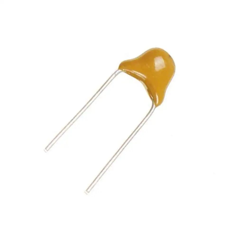
Ceramic Capacitor 220nf 50V

Polyester Capacitor 100nF 100V

Multilayer Ceramic SMD Capacitor MLCC SMD/SMT 100nF ±10% 50V X7R 0603

Super Capacitor Type C 5.5V 1.5F
2. What Is a Capacitor?
A capacitor stores electrical energy in an electric field. Inside are two conductive plates separated by an insulating layer called the dielectric. When you apply a voltage, charge collects on the plates. When the voltage drops, the capacitor releases that charge back into the circuit.
Three facts cover most of what you need:
- Capacitance is measured in farads (F). It tells you how much charge the capacitor holds per volt: C = Q ÷ V.
- Stored energy is E = ½ × C × V². A 1000 µF capacitor charged to 10 V stores ½ × 0.001 × 100 = 0.05 J.
- DC and AC: once charged, a capacitor blocks steady DC current. It passes changing (AC) signals, and the faster the change, the easier it passes. This is why capacitors both smooth power rails and couple or filter signals.
In a power supply, a capacitor works like a tiny local tank: it supplies current for an instant when the load asks for more than the source can deliver, and absorbs the excess when the load drops.
3. Capacitance Units: pF, nF and µF
Most capacitors are far smaller than one farad, so you will meet three small units. The micro sign µ is often written as u on shop listings and printed labels, so 10uF means 10 µF.
| Unit | Symbol | In farads | Conversion |
|---|---|---|---|
| Picofarad | pF | 10⁻¹² F | 1 nF = 1,000 pF |
| Nanofarad | nF | 10⁻⁹ F | 1 µF = 1,000 nF |
| Microfarad | µF | 10⁻⁶ F | 1 µF = 1,000,000 pF |
| Millifarad / farad | mF / F | 10⁻³ F / 1 F | Used for large and super capacitors |
Example: 0.1 µF = 100 nF = 100,000 pF. These are three ways of writing the same capacitor. If a circuit diagram says 100 nF and your shop lists 0.1uF, they are interchangeable.
4. Types of Capacitors
Capacitors are grouped by the dielectric, which sets their size, stability, polarity and typical use. Pick the type that matches the job:
| Type | Polarity | Typical values | Typical use | Browse |
|---|---|---|---|---|
| Ceramic (disc and MLCC) | No | 1 pF to 100 µF | Decoupling, filters, timing, high-frequency work | Ceramic and SMD capacitors |
| Aluminum electrolytic | Yes | 0.1 µF to 100,000 µF | Power supply smoothing, bulk storage, audio coupling | Polarized capacitors |
| Tantalum (solid, SMD) | Yes | 0.1 µF to 1000 µF | Compact, stable bulk capacitance on small boards | SMD capacitors |
| Film (polyester, polypropylene) | No | 1 nF to a few µF | Audio, filters, mains snubbers and suppression | Polyester capacitors |
| Super capacitor (EDLC) | Yes | 0.1 F to hundreds of F | Memory backup, short-term power, energy buffers | Super capacitors |
| Trimmer / variable | No | pF range | Tuning radio and oscillator circuits | All capacitors |
Ceramic capacitors
Ceramic capacitors have no polarity, a very low internal resistance (ESR) and work well at high frequency, which makes them the standard choice for decoupling. The dielectric code matters: C0G (NP0) is very stable and is used for timing and filters with small values. X7R is a good general choice but its capacitance changes with temperature. X5R, Y5V and Z5U give high capacitance in a small size, but the value can drop a lot with temperature and, importantly, with applied DC voltage. A 10 µF X5R chip rated 6.3 V can lose a large share of its capacitance when it works near that voltage.

Ceramic Capacitor 22pF 50V

Ceramic Capacitor 1nF 50V

Ceramic Capacitor 10nF 50V
Ceramic Capacitor 220nf 50V
Multilayer Ceramic SMD Capacitor MLCC SMD/SMT 100nF ±10% 50V X7R 0603

Multilayer Ceramic Capacitors MLCC – SMD/SMT 10uF ±10% X5R 25V 0603

Multilayer Ceramic Capacitors MLCC – SMD/SMT 4.7uF ±10 50V 1206
Aluminum electrolytic capacitors
Electrolytic capacitors reach large values for their size, so they smooth and store power. They have polarity, a tolerance of about ±20%, higher ESR than ceramics, and a limited life that gets shorter with heat. Choose a voltage rating well above the working voltage, and pay attention to the case size so it fits the board.

Capacitor 10uF 50V

chang Electrolytic Capacitor 100uF 50V 8x12mm
Capacitor 470uF 25V

Rubycon Aluminum Electrolytic Capacitor 25V 1000uF 10x20mm Made in Japan

chongX Capacitor 2200uF 50V 18x36mm

Rubycon Aluminum Electrolytic Capacitor 10uF 450V 10x20mm Made in Japan
Tantalum, film and super capacitors
Tantalum capacitors are small and stable but are sensitive to overvoltage and reverse voltage, so use them at about half of their rated voltage. Film capacitors (polyester and similar) are non-polar, stable and available for higher voltages, so they suit audio, filters and circuits with higher-voltage rails. A mains-rated suppression capacitor is a special film part: use only parts marked and rated for mains. Super capacitors store farads at low voltage (often 2.7 V to 5.5 V per cell), and are used for memory backup and short bursts of power.

Tantalum Capacitors – Solid SMD 10uF ±10% 6.3V Case-A 3216
Tantalum Capacitors – SMD/SMT 220uF ±20% 6.3V Case-A 3216
Polyester Capacitor 100nF 100V

Film Polyester Capacitor 1uF 63V
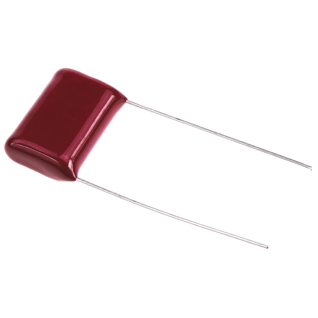
Polyester Capacitor 100nF 630V Pitch=9mm
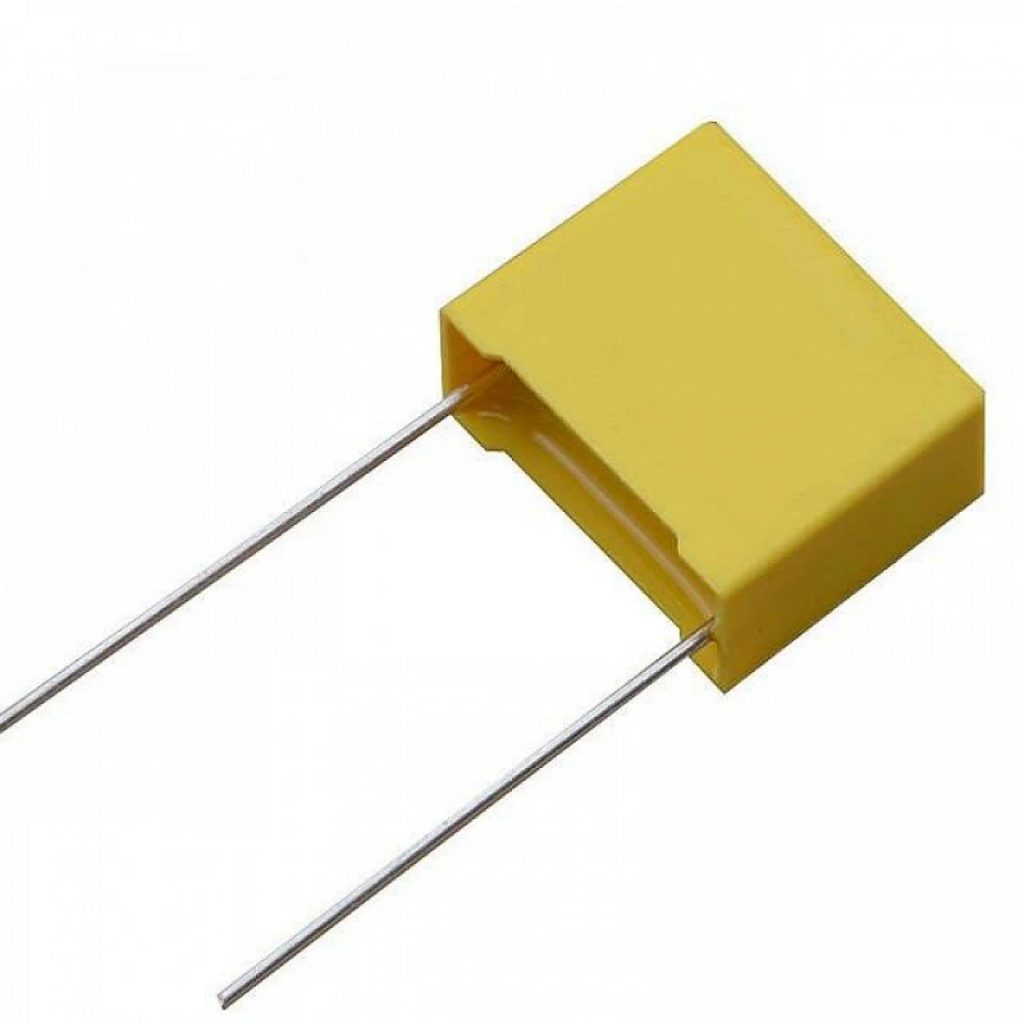
Suppression Capacitor 4.7nF 275V 10mm Through Hole
Super Capacitor Type C 5.5V 1.5F

SAMWHA Super Capacitor 500F 2.7V 35x62mm Made in South Korea
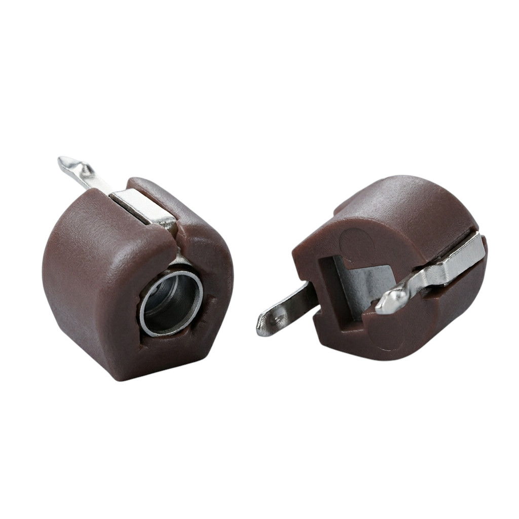
Trimmer Variable Capacitor 70pF 2Pin
5. How to Read Capacitor Codes (104, 103, 224)
Small ceramic and film capacitors have no room for long text, so they use a three-digit code. The first two digits are the value, the third digit is the multiplier (the number of zeros), and the result is in picofarads (pF).
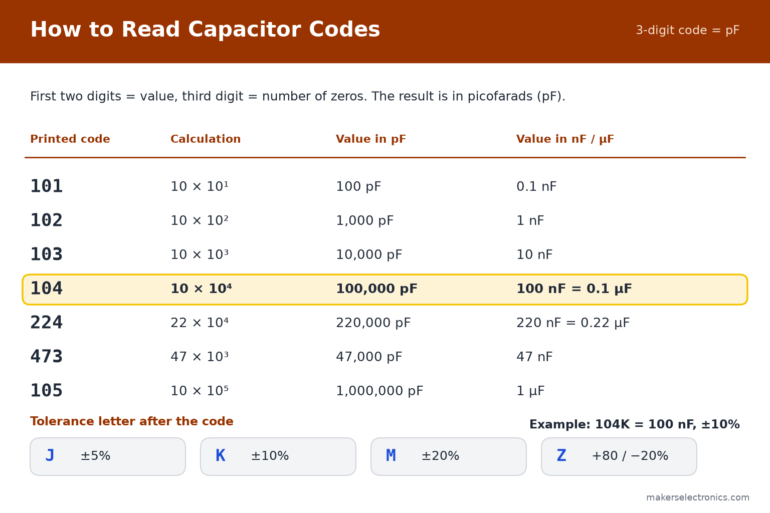
- 104 = 10 followed by four zeros = 100,000 pF = 100 nF = 0.1 µF. This is the most common decoupling value.
- 103 = 10,000 pF = 10 nF. 102 = 1,000 pF = 1 nF. 101 = 100 pF.
- 224 = 22 followed by four zeros = 220,000 pF = 220 nF = 0.22 µF. 105 = 1,000,000 pF = 1 µF.
- The letter R or a prefix marks the decimal point on some parts: 4n7 = 4.7 nF and 4u7 = 4.7 µF. A plain .1 or 0.1 often means 0.1 µF.
- A letter after the code gives the tolerance: J = ±5%, K = ±10%, M = ±20%, Z = +80% / −20%. So 104K = 100 nF ±10%. A number such as 50V or 63V next to it is the voltage rating.
Electrolytic capacitors are large enough to print their value in full, for example 1000 µF 25 V, together with the polarity stripe. SMD ceramic chips (MLCC) usually carry no marking at all, so keep them in their labeled bags: you cannot identify them by eye, and measuring them needs a meter with a capacitance range.
6. Polarity: Which Lead Is Which?
Ceramic and film capacitors have no polarity: either lead can go to either side. Electrolytic and tantalum capacitors are polarized and must be connected the right way. A reversed electrolytic capacitor can overheat, swell, leak or burst. The top of the can usually has a scored vent for this reason.

- Through-hole aluminum electrolytic: the stripe with minus signs marks the negative lead, and the longer lead is the positive one on a new part. On a board, the silkscreen usually shades the negative half of the circle.
- SMD tantalum: the stripe or bar marks the positive end, which is the opposite of aluminum electrolytics. Check the datasheet when in doubt.
- SMD aluminum can: a colored bar on the top marks the negative side, and the chamfered corner of the base is on the positive side.
- If you are not sure, measure with the multimeter’s diode or capacitance range, and check the board marking before you solder.
Never connect a polarized capacitor across an AC source, and never exceed its voltage rating. If a capacitor gets hot or bulges, disconnect power and replace it.
7. Voltage Rating and Derating
The voltage printed on a capacitor (for example 25 V) is the maximum working voltage. It is not the value it should be run at. The rating must always be higher than the highest voltage the capacitor will see, including spikes and ripple. A safe habit is to choose a rating of at least 1.5 to 2 times the working voltage. This is called derating, and it gives a longer life.
| Rail | Safe choice | Why |
|---|---|---|
| 3.3 V or 5 V logic | 10 V or 16 V | Leaves room for spikes; ceramics lose less capacitance |
| 9 V or 12 V | 25 V | At least twice the supply |
| 24 V | 50 V | At least twice the supply |
| Rectified 12 V AC (peak about 17 V) | 25 V or 35 V | A rectifier charges the capacitor to the peak, not the RMS value |
| Tantalum on a 5 V rail | 16 V or higher | Tantalum should run at about half its rating |
Ceramic capacitors have an extra effect. Their capacitance falls as the DC voltage across them rises, and the drop is bigger for high-capacitance parts in small packages. A 10 µF 6.3 V chip on a 5 V rail may deliver far less than 10 µF. For ceramics, choose a voltage rating well above the working voltage, or use a larger package, and check the manufacturer’s DC-bias curve if the exact value matters.
8. Decoupling: The 100 nF Rule
When a digital chip switches, it pulls short, sharp bursts of current. The power wire has resistance and inductance, so the supply voltage at the chip dips for a moment, and that can cause resets or random errors. A decoupling (bypass) capacitor placed right at the chip’s power pins supplies those bursts locally.
- Put a 100 nF (0.1 µF) ceramic capacitor between each supply pin and ground, as close to the chip as you can, with short connections. Pins that are far from the capacitor lose most of the benefit.
- Add a larger bulk capacitor (10 µF to 100 µF, electrolytic or large ceramic) where the power enters the board or a group of chips. It covers slower changes.
- Use both together: the small one answers fast spikes, the large one answers longer demands. A 100 nF capacitor in parallel with a 10 µF capacitor is a common pair.
On a breadboard, push the 100 nF capacitor into the same rows as the IC supply pin and its ground pin. With ESP32 and ESP8266 boards, Wi-Fi transmissions create current bursts, so a 100 µF to 470 µF capacitor close to the module’s supply is a common fix for random resets on weak USB supplies. See also our guide to buck converters and LDO regulators, which also need input and output capacitors. SMD 100 nF capacitors in 0603, 0805 and 1206 sizes are available in the SMD capacitors category.
Ceramic Capacitor 10nF 50V
Ceramic Capacitor 220nf 50V
Multilayer Ceramic SMD Capacitor MLCC SMD/SMT 100nF ±10% 50V X7R 0603
chang Electrolytic Capacitor 100uF 50V 8x12mm
Capacitor 470uF 25V
9. Smoothing Capacitors in Power Supplies
A rectifier turns AC into pulses of DC. A smoothing capacitor after it fills the gaps between pulses. The bigger the capacitor and the smaller the load current, the smaller the remaining ripple. A simple estimate is:
ΔV (ripple, peak to peak) ≈ I ÷ (f × C)
I is the load current in amperes, C is the capacitance in farads, and f is the ripple frequency. For a full-wave rectifier on a 50 Hz mains supply, the ripple frequency is 100 Hz. For a half-wave rectifier it is 50 Hz.
Example: a load of 0.5 A, a full-wave rectifier (100 Hz) and a target ripple of 1 V need C = 0.5 ÷ (100 × 1) = 0.005 F = 5,000 µF. Using 2,200 µF would give about 2.3 V of ripple.
| Load current | Target ripple | Capacitance needed at 100 Hz |
|---|---|---|
| 0.1 A | 1 V | 1,000 µF |
| 0.5 A | 1 V | 5,000 µF |
| 1 A | 1 V | 10,000 µF |
| 1 A | 0.5 V | 20,000 µF |
This is an estimate. A regulator after the capacitor (such as a 7805) needs its input voltage to stay above the regulator’s minimum even at the bottom of the ripple. In low-voltage supplies, add a small ceramic capacitor in parallel with the big electrolytic, because electrolytics are slow at high frequencies. Be careful: the capacitor also needs a voltage rating above the peak voltage (see section 7) and care while working with mains voltage. Browse polarized capacitors in many capacities and voltage ratings.
10. The RC Time Constant
When a capacitor charges through a resistor, the voltage does not jump up: it rises along a curve. The speed depends on the time constant:
τ = R × C
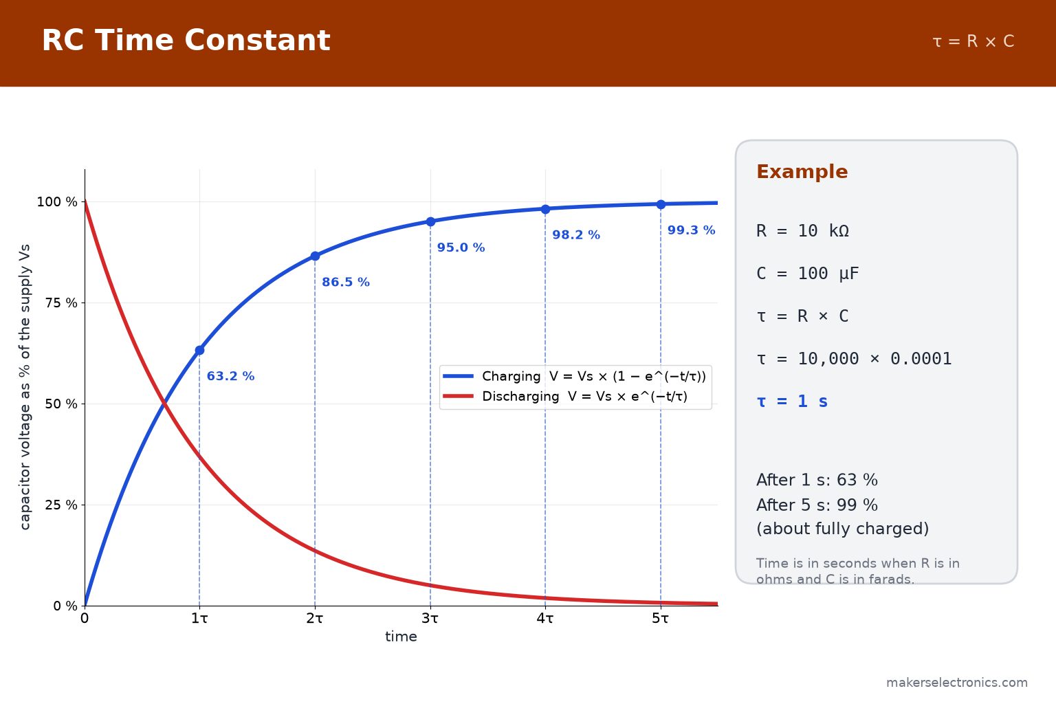
- After 1 τ the capacitor has charged to about 63% of the supply voltage. After 5 τ it is about 99% charged.
- Discharging is the mirror image: after 1 τ about 37% of the voltage is left, after 5 τ about 1%.
- With R in ohms and C in farads, τ is in seconds. Example: 10 kΩ × 100 µF = 10,000 × 0.0001 = 1 second.
Uses of the RC pair: a simple power-on reset delay, a button debounce filter, and a low-pass filter. The cutoff frequency of an RC low-pass filter is:
fc = 1 ÷ (2π × R × C)
Example: R = 10 kΩ and C = 100 nF gives fc = 1 ÷ (2π × 10,000 × 0.0000001) ≈ 159 Hz. Signals well above that frequency are reduced. For the resistor side of the pair, see our resistors guide.
11. Capacitors in Series and in Parallel
- In parallel the capacitances add: C = C1 + C2. Two 10 µF capacitors in parallel give 20 µF. The voltage rating stays the same as the lowest-rated capacitor.
- In series the total is smaller: 1 ÷ C = 1 ÷ C1 + 1 ÷ C2. Two equal capacitors in series give half the value: two 10 µF capacitors give 5 µF. Two equal capacitors in series can share a higher voltage, but only if it divides evenly between them. Without balancing resistors, do not rely on that for electrolytics.
Parallel is the more common trick. If a design needs 20 µF and you only have 10 µF parts, two in parallel do the job. A 100 nF capacitor beside a 10 µF capacitor also covers a wider frequency range, as in the decoupling section. Remember that electrolytics in parallel must still have the correct polarity, and each must have a rating above the working voltage.
12. How to Test a Capacitor with a Multimeter
- Disconnect power and discharge the capacitor. A large capacitor can hold a dangerous charge. Short its leads through a resistor of 100 Ω to 1 kΩ for a few seconds. Never short a charged capacitor directly. Capacitors inside mains-powered equipment can hold a dangerous charge for a long time: if you are not trained for that work, leave it to a professional.
- Remove it from the circuit, or at least lift one lead. Other parts in parallel give wrong readings.
- Set the meter to the capacitance range (a symbol like ⊣⊢). Touch the leads to the capacitor, observing polarity for electrolytics. The reading should be close to the marked value, within its tolerance (electrolytics are often ±20%).
- If the meter has no capacitance range, use the resistance range on a large electrolytic: the resistance starts low and climbs as the capacitor charges. A reading that stays near zero suggests a short, and one that never moves suggests an open capacitor.
- Check the body. A bulging top, leaking liquid or a discolored vent means the capacitor must be replaced, whatever the meter says.
A meter measures capacitance but not ESR (internal resistance), and an old electrolytic can show the right capacitance with a high ESR and still cause problems. For power-supply repair, a dedicated ESR meter is better. Many of the multimeters in our UNI-T multimeter range, and the multimeter category, include a capacitance range: see our multimeter guide for the basics. Fine SMD parts are easier to remove and refit with a soldering station.
13. Common Mistakes to Avoid
- Connecting an electrolytic or tantalum capacitor backwards.
- Using a capacitor whose voltage rating is too close to the supply, or equal to it.
- Reading 104 as 104 pF. It is 100 nF.
- Putting the decoupling capacitor far from the chip, or without a short ground connection.
- Using a 6.3 V ceramic chip on a 5 V rail and expecting its full marked capacitance.
- Using a general-purpose capacitor in a mains circuit instead of a part rated for it.
- Touching a large capacitor after switching off a power supply. Discharge it first.
- Treating a tolerance of ±20% on electrolytics as an error: it is normal.
14. Values to Keep in Your Kit
For Arduino, ESP32 and general electronics, these values cover most needs:
| Value | Type | Typical use |
|---|---|---|
| 22 pF | Ceramic | Load capacitors for 16 MHz crystals (check the crystal’s load capacitance) |
| 1 nF to 10 nF | Ceramic or film | Small filters, RC timing, signal coupling |
| 100 nF | Ceramic | Decoupling for every IC (the most used value) |
| 1 µF to 10 µF | Ceramic or electrolytic | Regulator inputs and outputs, local supply |
| 100 µF | Electrolytic | Bulk capacitor on a breadboard or board supply |
| 470 µF to 1000 µF | Electrolytic | Motors, servos, relays and Wi-Fi bursts |
| 2200 µF and above | Electrolytic | Power supply smoothing |
Browse the ceramic, polarized, polyester and super capacitor categories, or the full capacitors range. Current prices and availability are on each product page.
Ceramic Capacitor 22pF 50V
Ceramic Capacitor 10nF 50V
Ceramic Capacitor 220nf 50V
Capacitor 10uF 50V
chang Electrolytic Capacitor 100uF 50V 8x12mm
Capacitor 470uF 25V
chongX Capacitor 2200uF 50V 18x36mm
15. Frequently Asked Questions
What does 104 mean on a capacitor?
It means 10 followed by four zeros in picofarads: 100,000 pF = 100 nF = 0.1 µF.
Does a capacitor have polarity?
Ceramic and film capacitors do not. Aluminum electrolytic and tantalum capacitors do, and they must be connected with the right polarity.
Can I use a capacitor with a higher voltage rating?
Yes. A higher voltage rating is safe, but the capacitor is usually larger. The capacitance value should stay the same as in the design.
Can I use a capacitor with a higher capacitance than the design?
It depends. For decoupling and smoothing a bigger value is usually fine. For timing circuits, filters and some regulators, the value sets the behavior, so keep it close to the design, and check the regulator datasheet.
What is the difference between a ceramic and an electrolytic capacitor?
Ceramic capacitors are non-polar, low-ESR and good for high frequencies, with small values. Electrolytic capacitors are polarized and reach much larger values, which suits power smoothing, but have higher ESR and a limited life.
How far should the decoupling capacitor be from the chip?
As close as possible to the supply pin, with short traces or leads, because the benefit drops quickly as the distance grows.
Why did my electrolytic capacitor swell or burst?
Common reasons are reverse polarity, a voltage above the rating, heat, or old age. Replace it with a correctly rated part and check the circuit first.
How do I discharge a capacitor safely?
Disconnect the supply, then connect a resistor of 100 Ω to 1 kΩ across its leads for a few seconds, and verify the voltage with a multimeter.
16. Conclusion
A capacitor is easy to use once you know four things: read the value (104 = 100 nF), respect the polarity of electrolytic and tantalum parts, keep the voltage rating well above the working voltage, and place the decoupling capacitor close to the chip. With the RC time constant and the ripple formula you can also size capacitors for delays and power supplies instead of guessing.
When you are ready to build, browse ceramic capacitors, polarized capacitors, polyester capacitors, SMD capacitors and super capacitors at Makers Electronics.


Leave a comment
You must be logged in to post a comment.